- All
- Product Name
- Product Keyword
- Product Model
- Product Summary
- Product Description
- Multi Field Search

Views: 0 Author: Site Editor Publish Time: 2026-05-31 Origin: Site


Producing double-end studs poses a highly specific mechanical challenge. Manufacturers must balance material displacement across two distinct thread zones simultaneously. Doing this without compromising the unthreaded center demands absolute precision. Any slight variation creates structural weaknesses in the final component.
High-volume production becomes viable only when you deploy exceptionally precise Stud Molds during the cold forming process. Substandard tooling inevitably causes continuous runout issues, uneven threads, and frequent machine downtime. These disruptions derail manufacturing schedules and erode operational efficiency.
We provide technical buyers and production engineers a structured evaluation framework here. You will learn to assess mold design capabilities based on concentricity control, thread length accuracy, and long-term forming stability. This approach ensures your production safely meets strict industry standards while optimizing daily factory output.
Concentricity limits scrap: Exact alignment between die cavities prevents runout errors and ensures compliance with ASME standards.
Material displacement dictates thread length: Superior mold design calculates exact volume flow to prevent thread underfill or flash.
Stability equals predictable tool life: Controlled extrusion pressures in cold heading dies prevent premature insert cracking and reduce machine downtime.
Verification over promises: Evaluate tooling suppliers based on their first-article inspection data and demonstrable control over forming variables, not just theoretical tool life claims.
Substandard molds introduce hidden operational costs across the production floor. You will first notice these costs as high scrap rates. Minor runout errors multiply rapidly during high-speed cold forming operations. Frequent tool changeovers drain productivity further. Operators must stop machines, replace cracked inserts, and recalibrate alignment. Rejected lots happen routinely because thread lengths fall out of tolerance limits. These hidden penalties destroy overall manufacturing margins.
You can define a successful tooling implementation by measuring specific operational outcomes. The tooling must deliver repeatable dimensional accuracy across hundreds of thousands of strikes. Maintenance intervals should remain entirely predictable. The final parts must adhere strictly to ASME B18.31.1M and B18.31.2 specifications. Meeting these standards requires robust upfront engineering.
Investing in premium Fastener Molds offsets higher initial costs through massive operational savings. High-quality molds drastically reduce raw material waste. They prevent the flashing and underfilling errors common in cheap tooling. Machine uptime increases because operators perform fewer emergency die replacements.
Operational Metric | Standard Mold Impact | Precision Mold Impact |
|---|---|---|
Scrap Rate | High; frequent runout and dimension errors. | Low; exact cavity alignment ensures compliance. |
Machine Uptime | Inconsistent; unpredictable insert failures. | High; scheduled and predictable maintenance. |
Standard Compliance | Borderline; often fails ASME length tolerances. | Strict; guaranteed adherence to B18.31.1M/B18.31.2. |
Common Mistake: Buyers often evaluate tooling based purely on the initial quote. Ignoring the operational disruption caused by poorly designed molds leads to continuous production headaches.
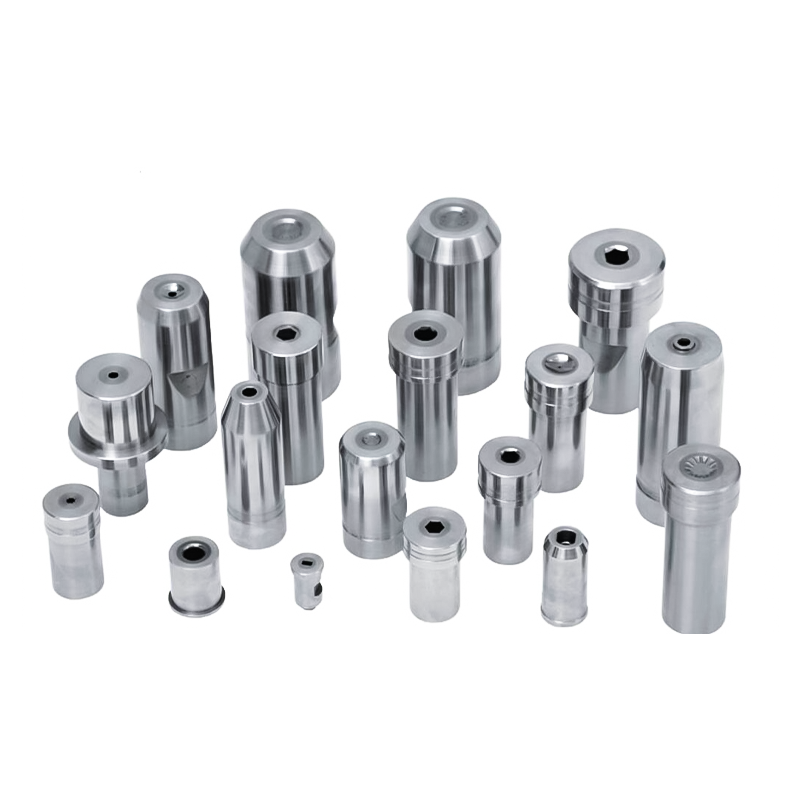
Maintaining a shared axis between two separate thread sections and an unthreaded body creates a massive engineering challenge. During the cold heading stroke, immense forces attempt to shift the material laterally. If the tooling allows even microscopic lateral movement, the entire double-end stud suffers from runout. The two threaded ends will no longer share a true center line. This misalignment guarantees failure during automated assembly down the line.
Advanced mold designs solve this through rigorous cavity alignment. Engineers incorporate high-precision locating features directly into the die blocks. They utilize rigid guide systems to prevent any axial shift during the high-velocity impact stroke. These features force the material to displace evenly around the central axis.
When you evaluate suppliers, ask specific questions about their machining capabilities. Demand to know their machining tolerances for die blocks and inserts. You should also ask how they verify concentricity during the design phase. Reliable partners use advanced 3D modeling to simulate the tooling fit before they cut any steel.
However, we must introduce a necessary reality check. No mold eliminates machine-side wear completely. Older cold heading machines exhibit ram droop or platen shift over time. Cold Heading Dies must account for this inevitable press degradation. Top-tier tooling designs build in micro-adjustability. Operators can fine-tune the alignment at the machine to compensate for mechanical wear, keeping concentricity locked in.
Thread length precision depends entirely on volume distribution logic. The mold geometry must actively manage material flow during the impact stroke. It must push the exact volume of alloy outward so both ends reach the correct thread blank diameter and length. If the mold displaces too much material, the center body starves and becomes undersized. If it displaces too little, the threads will not form fully during the subsequent rolling process.
Managing the transition zones properly is equally crucial. The mold must shape the chamfer and runout areas perfectly. A clean transition prevents stress risers in the final assembled stud. Stress risers invite catastrophic fatigue failures when the stud faces dynamic operational loads in the field.
Strict standard compliance demands this level of volume control. Tooling design directly impacts your ability to meet ASME dimensional charts for continuous and double-end studs. ASME tolerances leave no room for trial-and-error material displacement.
You face severe implementation risks if you accept "one-size-fits-all" die designs. Mold geometries require tailoring to the specific yield strength and flow characteristics of your chosen alloy. A die designed for low-carbon steel will fail miserably if you attempt to run 300-series stainless steel through it.
Symptom | Likely Mold Design Flaw | Actionable Solution |
|---|---|---|
Thread Underfill | Insufficient extrusion cavity volume. Material cannot reach the required blank diameter. | Recalculate volume flow; increase extrusion angle to push more material outward. |
Center Body Starvation | Excessive material pushed to thread ends. Center diameter falls below tolerance. | Restrict thread end cavity flow; balance draft angles. |
Heavy Flashing | Poor mating between die segments; excessive cutoff volume. | Improve cavity alignment tolerances; adjust cutoff length precisely. |
Extrusion pressure distribution dictates forming stability. When forming double-end studs, pressure spikes easily inside the die cavity. Proper draft angles prevent excessive pressure buildup. Excellent surface finishes allow the material to glide rather than stick. Precise insert geometries distribute the impact force evenly across the tooling.
Material selection for the tooling itself determines how well the mold handles these pressures. Engineers must match specific tool materials to designated wear zones.
Tungsten Carbide Inserts: Placed in high-impact and high-wear zones. They offer extreme hardness and resist deformation under immense extrusion pressures.
High-Speed Tool Steels (e.g., M2 or CPM variants): Used for supporting blocks and outer casings. They provide necessary toughness and flex to absorb the shock of the heading stroke without shattering.
Thermal and frictional realities complicate high-speed forming. Rapid metal deformation generates intense heat. High-quality molds incorporate optimal lubrication channels to flush coolant directly into high-friction zones. Surface coatings like PVD (Physical Vapor Deposition) or CVD (Chemical Vapor Deposition) add a critical barrier. They reduce friction, prevent galling, and maintain dimensional stability across thousands of cycles.
Best Practice: Rely on predictable degradation models. Trustworthy tooling partners provide realistic wear models based on your material and machine speed. They never promise indefinite die life. They tell you exactly when to replace inserts before a catastrophic failure ruins an entire production run.
Vendor sourcing logic must move far beyond basic pricing comparisons. A cheap mold guarantees expensive production delays. You need a framework for assessing a manufacturer's engineering depth and true production capabilities. You should look for partners who act as problem solvers rather than simple part suppliers.
Use these key shortlisting questions to evaluate potential tooling partners:
Can they provide FEA (Finite Element Analysis) simulations for material flow prior to cutting steel? Visualizing material displacement virtually eliminates guesswork and reduces physical prototyping iterations.
What is their protocol for validating the mold against your specific cold heading machinery? A good supplier accounts for your specific machine's ram speed, tonnage, and potential wear.
Do they have documented experience designing tools specifically for ASME-compliant double-end studs? Generic fastener experience does not translate to the strict tolerances required for double-end configurations.
Take actionable next steps once you shortlist candidates. Recommend a technical consultation focused on a specific, problematic part number from your current catalog. Ask them to diagnose the issue and propose a mold redesign. This test quickly reveals their troubleshooting methodology and engineering competence.
Successful double-end stud manufacturing remains a direct output of upfront mold engineering. You cannot inspect quality into a poorly formed part. You must engineer precision into the tooling from day one.
Controlling concentricity completely mitigates scrap risks and assembly failures.
Mastering material displacement ensures perfect thread lengths and prevents body starvation.
Managing extrusion pressures stabilizes production and makes tool maintenance predictable.
Engineers and procurement teams must stop accepting subpar tooling. We encourage you to submit your complex part prints or current tooling challenges for an expert technical review. Upgrading your mold design is the fastest path to stabilizing high-volume stud production.
A: Poor concentricity usually stems from tool misalignment, worn die blocks, or uneven material displacement. If the mold cavities lack rigid guide systems, the immense impact force causes lateral shift. Machine-side wear, like ram droop, also contributes to this error if the mold lacks micro-adjustability features.
A: Cold heading dies control body length by managing the strict relationship between the initial cutoff volume, extrusion geometry, and die cavity limits. The mold carefully calculates material flow, restricting excess alloy from flooding the thread zones so the unthreaded center maintains precise dimensions.
A: Tool life varies significantly based on multiple variables rather than a fixed absolute number. The specific material grade you form, the condition of your heading machine, and the tooling coatings (like PVD) dictate lifespan. Premium molds offer predictable wear models, allowing scheduled insert replacements instead of unexpected failures.
A: No. While modular inserts exist, relying on them for multiple thread lengths often compromises precision. Dedicated tooling ensures exact volume displacement and maintains the tight tolerances required by ASME standards. Modular setups introduce slight misalignments that cause runout and length errors.