- All
- Product Name
- Product Keyword
- Product Model
- Product Summary
- Product Description
- Multi Field Search

Views: 0 Author: Site Editor Publish Time: 2026-07-06 Origin: Site


Shifting from low-volume automotive prototyping to high-volume, standardized production requires rigorous tooling evaluation. Precision engineering dictates the ultimate success of every manufacturing run. Manufacturers face immense pressure to deliver consistent components across millions of operating cycles. Substandard die design often leads to accelerated wear and dangerous tolerance drift, such as springback or edge shear. Such structural flaws cause unacceptable downtime during critical manufacturing cycles. They frequently disrupt the entire supply chain and can compromise vehicle safety. We will establish an evidence-based framework for specifying automotive tooling and evaluating critical edge or forming processes. You will discover practical strategies to manage material flow and prevent defect accumulation. Finally, you will learn how to select manufacturing partners capable of strict, long-term quality compliance.
Standardizing production requires aligning die architecture (progressive vs. transfer) with the structural complexity of the automotive component.
Mitigating edge shear and tolerance accumulation in blanking relies on precise clearance calculations and proper ejector mechanics.
Prolonging the lifecycle of cold working molds depends on specifying premium internal components and establishing rigorous maintenance protocols.
Supplier shortlisting must prioritize total cost of ownership (TCO), IATF 16949 compliance, and robust Design for Manufacturing (DFM) capabilities over baseline tooling quotes.
You must evaluate die architecture based on strict production volume constraints and specific part geometry. Progressive dies feed a continuous metal coil through sequential stations. Each station performs a distinct cutting or bending operation. This setup excels for high-volume production of smaller, structurally simple automotive brackets. Transfer dies operate differently. They process individual metal blanks. Mechanical transfer fingers move the part from station to station. You should choose transfer dies when manufacturing complex chassis components or large body panels. They offer greater freedom for deep drawing and multi-angle forming.
Modern automotive lightweighting initiatives rely heavily on Advanced High-Strength Steels (AHSS) and specialized aluminum alloys. These materials introduce severe manufacturing constraints. You must adapt die specifications to handle increased tensile strength and unpredictable yield behaviors. AHSS requires specialized tool coatings and robust die structures to prevent catastrophic tool failure. Aluminum alloys present a different challenge. They frequently cause galling, where material adheres to the tooling surface. Engineers must apply specific lubricants and polish die surfaces to mirror finishes to mitigate this risk.
Stamping heavy-gauge automotive plates demands highly durable tooling. You must distinguish heavy-duty Cold Working Molds from standard sheet metal tooling. Standard tooling handles thin-gauge panels adequately. However, thick suspension brackets and structural reinforcements generate immense localized pressure. Cold working applications require premium tool steels, such as D2 or powdered metallurgy steels. These materials resist abrasive wear and withstand repeated impact without fracturing. Proper integration ensures uninterrupted production during rigorous, high-tonnage stamping operations.
Analyzing upfront tooling feasibility requires a comprehensive risk assessment framework. We recommend evaluating technical constraints before committing to a specific die architecture. Consider the following sequentially numbered evaluation steps:
Assess the projected annual production run rates against tool fatigue limits.
Identify the frequency of expected maintenance intervals based on material hardness.
Determine the required press tonnage and verify facility floor capacity.
Evaluate the geometry for potential forming bottlenecks, such as extreme bend radii.
The chart below compares the functional limits of progressive and transfer die architectures.
Feature | Progressive Die Architecture | Transfer Die Architecture |
|---|---|---|
Optimal Part Size | Small to medium components | Large, complex panels |
Production Speed | Very high (strokes per minute) | Moderate to high |
Material Feed System | Continuous coil feed | Individual blank transfer |
Geometric Flexibility | Limited by carrier strip | High (multi-axis forming) |
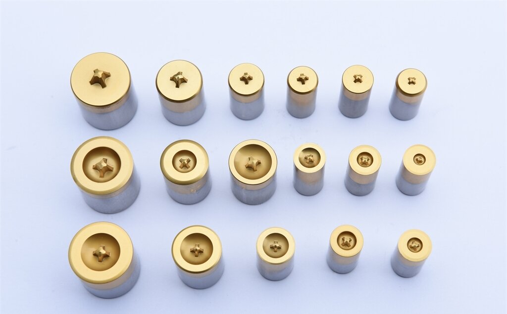
Standard blanking fractures the metal, leaving a distinct shear band and a rough break zone. This traditional method suits non-critical structural brackets perfectly. However, certain automotive applications demand strict dimensional accuracy. Gear teeth and safety-critical latches require completely smooth edge conditions. For these profiles, you should specify fine blanking. Fine blanking applies specialized V-ring pressure to clamp the material tightly. It forces the metal to extrude rather than fracture. This process delivers tightly toleranced, cleanly sheared edges without requiring expensive secondary machining.
High-speed repetitive cycling introduces severe friction and stress into tooling internals. Over time, this stress degrades the cutting edges. Managing these wear dynamics prevents sudden tool failure. You must monitor thermal expansion during continuous runs. Heat builds up rapidly at the cutting interface. Excessive heat degrades the temper of the cutting punch. Implementing targeted cooling strategies and applying extreme-pressure lubricants will effectively disperse thermal loads.
Engineering the correct internal punch geometry prevents destructive operational failures. You must carefully specify your Punch Pin Ejector Pin configuration. Improper placement leads to slug pulling. Slug pulling occurs when the scrap metal pulls back out of the die cavity and rests on the stamping strip. The next press stroke will crush this slug into the tooling, causing catastrophic damage. Optimizing ejector pin spring rates ensures clean part ejection. Correct sizing minimizes tool binding and keeps the production line moving smoothly.
Establishing realistic limits for burr height prevents downstream assembly issues. Automotive safety standards dictate strict shear band ratios. A dull punch creates excessive burrs, which pose safety hazards and interfere with welding operations. We recommend the following practices for tolerance control:
Calculate die clearance as a strict percentage of material thickness.
Monitor edge quality visually and tactilely during frequent quality checks.
Replace punches before burr height exceeds 10% of the material gauge.
Implement automated optical inspection for safety-critical blanked components.
Automotive geometries frequently suffer from material rebound, commonly known as springback. Once the press opens, the formed metal attempts to return to its original flat state. You must anticipate this reaction during the initial Design for Manufacturing (DFM) phase. Utilizing Finite Element Analysis (FEA) provides critical predictive data. FEA software simulates the exact stresses applied to the blank. Engineers use this data to over-bend the tooling geometry intentionally. This compensation ensures the panel rests at the correct dimensional tolerance after springback occurs.
Deep-drawn components require precise material flow control to prevent tearing or wrinkling. If the material flows too quickly, wrinkles form on the flange. If it flows too slowly, the panel thins out and splits. Controlling friction is the key to flow optimization. You must balance binder pressure accurately. The binder holds the outer edge of the blank while the punch draws the center. Applying the correct lubrication film further aids material displacement. Modifying the draw bead geometry also helps restrict or encourage flow in highly localized zones.
Even the most perfectly engineered tooling experiences gradual wear. Taking a massive transfer die completely offline for a major overhaul disrupts production schedules. You need a method to manage localized wear dynamically. The strategic insertion of precision Shims plays a critical role here. Operators use these ultra-thin metal spacers to fine-tune die clearance directly in the press. They allow technicians to micro-adjust forming blocks. This practice compensates for minor dimensional drift and maintains part accuracy without requiring a full tool teardown.
Tooling surfaces must never compromise the final formed automotive panel. Exterior body panels demand flawless cosmetic finishes, known as Class-A surfaces. Even minor imperfections on the die face will transfer directly onto the metal sheet. You must mandate stringent polishing protocols for all forming blocks. Additionally, structural components require intact surface integrity to prevent premature fatigue cracking. Scoring or deep scratching during the forming process creates stress concentrators. Eliminating galling and maintaining immaculate tool surfaces guarantees both cosmetic perfection and structural reliability.
Moving past the initial design phase requires a strict focus on equipment degradation. Tool wear happens invisibly during the initial stages of a production run. You must calculate the rates of tool degradation, expected press downtime, and subsequent scrap generation. Relying purely on reactive maintenance guarantees failure. When a die crashes due to neglected wear, the resulting downtime impacts the entire automotive assembly plant. Tracking stroke counts accurately provides baseline data for component fatigue analysis.
Assessing component durability determines the true lifecycle of your tooling internals. High-impact zones require premium material selection. Utilizing standard tool steel saves money initially but guarantees frequent sharpening interruptions. Upgrading to solid carbide inserts for critical cutting edges extends the run time between sharpening cycles significantly. Carbide resists abrasive wear far better than traditional steels. You must analyze which specific die stations endure the most friction and upgrade those specific inserts accordingly.
Maintaining Production Part Approval Process (PPAP) conformity over the program's life requires disciplined maintenance protocols. You must establish clear, non-negotiable intervals for tooling service. A robust maintenance schedule includes the following critical actions:
Standardizing sharpening intervals based on exact stroke counts, not visual guesses.
Performing routine shim adjustments to maintain precise punch-to-die clearances.
Scheduling mandatory ejector pin replacements before metal fatigue causes snapping.
Conducting ultrasonic cleaning of die blocks to remove embedded metal shavings.
Choosing a manufacturing partner requires verifying their internal engineering capabilities. You must confirm their ability to run accurate forming simulations independently. A competent supplier provides actionable geometry optimizations before any steel is cut. They should review your CAD models and identify problematic bend radii or deep draw risks. This collaborative DFM process prevents expensive tooling modifications later. Avoid vendors who accept flawed designs without offering technical pushback.
Automotive manufacturing demands strict adherence to global quality standards. You must mandate compliance with IATF 16949. This certification proves the supplier maintains rigorous defect prevention and continuous improvement systems. Furthermore, demand transparent First Article Inspection (FAI) reporting. The supplier must provide comprehensive metrology data proving the initial parts meet every dimensional tolerance. A robust quality infrastructure ensures subsequent production runs match the approved master sample exactly.
Evaluating a vendor's physical scalability prevents future supply chain bottlenecks. You must assess their maximum press tonnage limits. Ensure they possess the correct overhead handling equipment to maneuver heavy dies safely. Heavy-duty Stamping Dies require specialized rigging and robust press beds. Additionally, investigate their contingency planning. A reliable partner maintains redundant press lines to handle unexpected high-volume spikes or sudden equipment failures.
Initiating a formal technical design review marks the first step in successful procurement. Gather your engineering team and the shortlisted suppliers. Request an itemized, transparent tooling breakdown. This breakdown should separate the costs of raw tool steel, internal components, and engineering labor. Transparent documentation allows you to verify they are specifying the premium materials required for long-term automotive production.
Sourcing automotive stamping dies remains a rigorous exercise in continuous risk management. You must balance precise engineering requirements, such as blanking clearances and forming simulations, with highly durable internal components. Implementing predictive maintenance prevents catastrophic tool failure and ensures long-term dimensional accuracy. We strongly recommend prioritizing vendors who treat die creation as an ongoing engineering partnership rather than a simple transactional purchase. Initiate a comprehensive DFM review with a qualified engineering team today to validate your component manufacturability and secure your production strategy.
A: Stroke count, material gauge, and maintenance protocols strictly dictate tool longevity. Stamping standard mild steel yields millions of cycles with proper lubrication. However, processing AHSS or heavy-gauge aluminum accelerates wear, reducing the lifespan to hundreds of thousands of cycles unless you utilize premium carbide inserts and rigorous maintenance.
A: Precision shims allow technicians to micro-adjust die components directly inside the press. They compensate for incremental metal wear and maintain exact dimensional accuracy. This localized tuning prevents the need for complete, time-consuming tool rebuilds, drastically improving overall lifecycle efficiency.
A: You should specify fine blanking for profiles demanding 100% cleanly sheared edges and extreme flatness. Safety-critical latches and gear teeth require these properties. Fine blanking extrudes the metal tightly, eliminating the rough fracture zone and bypassing the need for secondary machining.
A: Premature snapping or galling usually stems from improper heat treatment or inadequate die clearance. Poor lubrication also increases friction drastically. Misalignment during the press stroke generates lateral stress, which snaps ejector pins and damages the core die blocks.