- All
- Product Name
- Product Keyword
- Product Model
- Product Summary
- Product Description
- Multi Field Search

Views: 0 Author: Site Editor Publish Time: 2026-08-14 Origin: Site


In high-volume fastener production, automated machines strike metal thousands of times per minute. These intense operations demand absolute perfection from every tooling component. Tooling failure, dimensional inconsistency, and machine downtime plague many cold heading operations. These headaches almost always trace back to sub-optimal die manufacturing. Procurement and engineering teams face a rigorous challenge today. Evaluating a tooling partner requires looking far beyond unit cost. You must deeply understand their strict adherence to advanced metallurgical and machining standards. Poorly made tools shatter under pressure. Properly engineered dies withstand extreme mechanical stress. This article details the critical stages of the cold heading dies manufacturing process. We outline a reliable framework for evaluating supplier capabilities. You will discover practical methods to mitigate production risks. We will also show you how to maximize tool life effectively.
Engineering Pre-computation: Successful die manufacturing relies heavily on CAD/CAM simulation to predict stress distribution and prevent premature fatigue.
Material and Treatment Strictness: The performance of cold working molds is dictated by precise carbide or tool steel selection coupled with tightly controlled heat treatment.
Fabrication Precision: Advanced CNC and wire EDM operations are non-negotiable for achieving the micro-tolerances required in modern custom dies.
Verifiable Quality: Final inspection must go beyond visual checks, utilizing Coordinate Measuring Machines (CMM) and surface finish analysis to guarantee dimensional stability.
The foundation of reliable tooling begins long before any metal is cut. Engineering and design criteria dictate the eventual success of the entire production run. Creating precision molds requires rigorous upfront computation.
Engineers must first conduct a thorough application analysis. We start by assessing the formed part's material. Forming standard carbon steel requires a different baseline tooling toughness compared to forming aerospace alloys. You must establish this baseline toughness early. Next, engineers utilize Finite Element Analysis (FEA). FEA accurately simulates metal flow during the heading process. It pinpoints high-stress concentration areas within the die geometry. By identifying these zones, you can reinforce weak points to prevent premature fatigue.
Once simulations conclude, the drafting phase begins. Technical experts translate part prints into actionable die schematics. CAD/CAM integration ensures absolute fidelity between the digital model and the machining equipment. Evaluating a manufacturer’s design capability requires scrutiny here. Look for transparent assumptions in their design files. They should clearly justify draft angles, corner radii, and clearance tolerances. Minor calculation errors here cause major material flow problems later.
Material selection serves as the physical backbone of the die. You must match the die material to specific production volume and pressure requirements. Different applications demand different metallurgical properties.
Material Type | Key Characteristic | Ideal Application |
|---|---|---|
Tungsten Carbide | Extreme wear resistance | High-volume abrasive wear scenarios |
High-Speed Tool Steel (M2) | Balanced toughness and wear | Medium-run production with moderate impact |
High-Speed Tool Steel (M4) | Superior impact resistance | Heavy forming requiring fracture resistance |
Best Practice: Always align your material choice with the mechanical severity of the forming operation. Using carbide for high-impact applications often leads to immediate shattering.
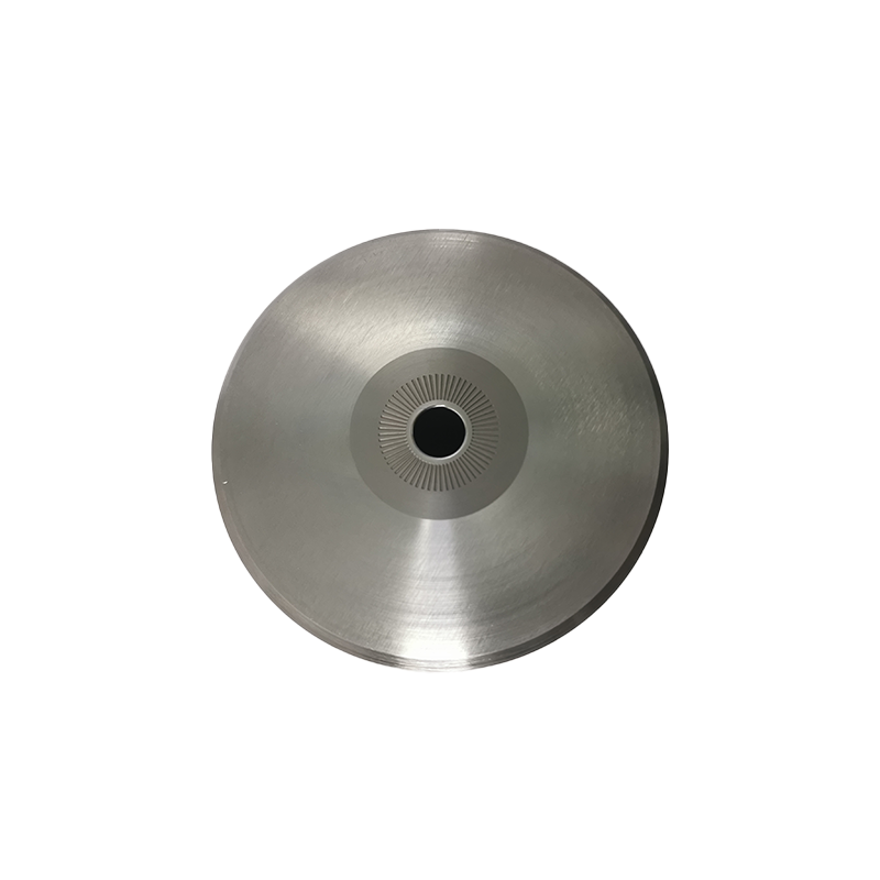
Translating digital designs into physical tooling requires immense control. The machining stages in die manufacturing separate premium suppliers from average shops.
The fabrication phase starts with blank preparation. Machinists perform initial turning and milling. This establishes the foundational shape of the die block. It is highly important to leave exact machining allowances at this stage. Metal expands and contracts during thermal processing. These allowances account for dimensional shifts during subsequent heat treatment.
Standard cutting tools fail when faced with ultra-hard materials or intricate internal shapes. Therefore, facilities utilize Wire EDM and Sinker EDM. These machines use electrical discharges to cut complex internal geometries. Traditional cutting tools simply cannot achieve these micro-profiles. You must use an evaluation lens when reviewing a supplier. Assess their EDM wire tolerance capabilities. Check their surface finish quality using Ra values. A poor surface finish creates friction points. Friction points inevitably lead to micro-cracking under heading pressure.
After thermal processing hardens the metal, final shaping occurs. Technicians perform jig grinding and cylindrical grinding post-heat treatment. This step removes the previously left machining allowances. It achieves exact concentricity across the die profile. It also guarantees adherence to tight tolerance requirements.
Common Mistake: Rushing the EDM process with high-amperage burns creates a thick "white layer" on the metal surface. This recast layer is highly brittle and causes rapid tool failure.
Even perfectly machined steel fails if its internal structure remains weak. Heat treatment fundamentally alters the molecular structure of cold working molds.
The criticality of thermal processing cannot be overstated. Premium facilities rely on controlled atmosphere vacuum furnaces. These specialized furnaces prevent surface oxidation. They also eliminate decarburization during the hardening process. Decarburization strips carbon from the surface, leaving it soft and useless. Engineers must carefully balance hardness (HRC) with fracture toughness. High hardness resists wear but increases brittleness. Balancing these traits prevents catastrophic die shattering under intense cold heading pressures.
Quenching hardens the steel but introduces massive internal stress. To solve this, manufacturers implement multiple tempering cycles. These cycles involve reheating the steel to a lower temperature. Tempering relieves internal residual stresses generated during the quenching phase. Skipping or shortening a temper cycle guarantees a cracked die.
Surface engineering provides a final layer of defense. Technicians often apply PVD (Physical Vapor Deposition) or CVD (Chemical Vapor Deposition) coatings. Popular coatings include TiN (Titanium Nitride) or TiAlN (Titanium Aluminum Nitride). Consider the ROI perspective when evaluating coatings. You must weigh the upfront cost of coatings against operational savings. Coatings drastically reduce galling. They significantly extend tool life in high-speed cold working applications.
Trusting a machining process without verification is a massive risk. Robust quality assurance protocols ensure your custom dies perform exactly as engineered.
Visual checks are entirely insufficient for modern tooling. Quality teams rely on CMM (Coordinate Measuring Machines). CMM validates that the complex profiles of the custom dies match the original CAD models. These machines measure deviations down to the micron level. Any discrepancy triggers an immediate rejection.
Dimensional accuracy handles shape, but surface finish handles friction. Technicians conduct surface roughness testing using sensitive profilometers. Smooth surfaces ensure optimal metal flow during the heading process. Quality assurance also requires Non-Destructive Testing (NDT). Methods include ultrasonic testing or magnetic particle inspection. NDT penetrates the metal block to verify the absence of sub-surface micro-fractures. Hidden fractures act as ticking time bombs on the production floor.
Documentation serves as your ultimate decision-stage criteria. A reliable partner never hides their process data. They should proactively provide full traceability reports. You should expect material certifications proving steel origin. They must supply heat treatment logs detailing furnace temperatures. Finally, they should deliver final inspection dimensional reports mapping the CMM results.
Securing a capable tooling partner requires a systematic evaluation strategy. You must ask difficult questions about their internal processes.
Technical Capability & Equipment: Investigate the facility directly. Does the facility possess in-house vacuum heat treatment? Do they operate multi-axis EDM machines? Find out if they outsource critical steps. Outsourcing increases lead-time and significantly raises QA risks.
Prototyping & Scalability: Test their production flexibility. Can the supplier efficiently transition from a single test die to a high-volume tooling program? They must demonstrate scalability without any loss of consistency.
Engineering Support: Look for partners who act as consultants. They should offer comprehensive failure analysis on existing dies. Avoid suppliers who merely offer "build-to-print" services without questioning the design. True manufacturers act as problem-solvers for tooling longevity.
The cold heading dies manufacturing process is far more than simple metal cutting. It requires a highly controlled sequence of engineering, metallurgy, and sub-micron machining. Tooling stands as the heartbeat of any fastener production line. Skimping on the evaluation of your die manufacturer inevitably leads to higher per-part costs. You will suffer excessive machine downtime and constant tooling replacement. Take action today to protect your production efficiency. Audit your current tooling failure rates closely. Request a technical consultation or a sample die inspection from certified manufacturers. This simple step establishes a benchmark for precision and quality.
A: The timeline varies based on geometry complexity and material selection. It typically ranges from 2 to 6 weeks. Manufacturers with comprehensive in-house capabilities significantly reduce lead times. Suppliers who outsource heat treatment or specialty coatings always experience longer delays.
A: Most premature failures stem from improper material selection. Inadequate heat treatment also causes severe brittleness. Additionally, poor surface finish creates friction points. This leads to galling and excessive friction, which quickly destroys the die cavity under heading pressure.
A: Carbide offers superior wear resistance for high-volume, long-run production. However, it remains highly brittle. Tool steel, like M4 or PM grades, offers better impact resistance for heavy forming operations. Tool steel wears out faster than carbide. Selection depends strictly on the application's severity.